ACPD – Alternating Current Potential Drop Precision crack depth measurement
Determine orientation and depth of a surface breaking crack
Benefits for client:
- Precisely measure depth of a normal, oblique, or curved surface breaking cracks.
- Provides orientation of inclined cracks with ±10° resolution in steel. (Limitations in non-Fe materials)
- Cost saving by avoiding repairs when a measured depth is less than a permitted engineering critical crack size.
- Eliminate MT while stagewise weld repairing by measuring accurate crack depth on mining heavy machinery.
- Higher precision of measurement than traditional ET, ECA or ACFM.
- Unlike ET, ECA, UT, RT; the width of the crack has almost no influence on the measurement.
- Suitable for measuring hot rolled linear discontinuities such as stringers, laps on which ACFM or ECA are not accurate because of the trapped high temp. oxide.
- Environmental sustainability by eliminating chemical usage.
Features:
- Characteristics curve for material properties under test can be created in the instrument to measure actual cracks accurately.
- Measurement reproducibility of ±1 mm for 100mm crack depth.
- Single or continuous assessment at 1 measurement/second speed.
- 300 batches comprising 3850 measurements can be stored for a longer crack assessment.
- Portable 225g, pocket sized handheld battery operated,
Applications:
- Precise measurement of crack depth after VT, MT & PT findings.
- Condition monitoring or growth rate assessment of known cracks in bridges, structures, pressure vessels, pipelines, heavy machinery, rails, aged bogies, rolling stock, axles, gears, etc.
- Useful on Austenitic and duplex stainless-steel cracks (Reference block is required)
- Complimentary depth measurement method with VT, MT, PT, RT, UT, ET, ECA, ACFM, LRUT, MFL
Principle:
- ACPD probe is positioned on the test surface with its spring loaded, gilded contact pins held firmly just outside of the edges of the crack. One contact pin on the LHS and the other on the RHS of the crack width.
- A constant alternating current is passed into the test surface (between current poles) which forces the alternating current because of skin effect to flow along the contour of the crack.
- A crack acts like an electrical resistance to the current flow thus affecting the voltage for an applied constant alternating current circuit.
- The potential drop (voltage) between two poles positioned left & right to the crack is expressed as proportional to the crack depth. Note – Theoretically, crack depth is not linear to the potential drop. Hence the instruments advanced microprocessor applies correction factor at different voltage level.
- Instrument is validated on a reference block containing an artificial 0 to 20mm tapered notch. Deviations caused by worn pins or extreme temperatures can be compensated by re-calibration.
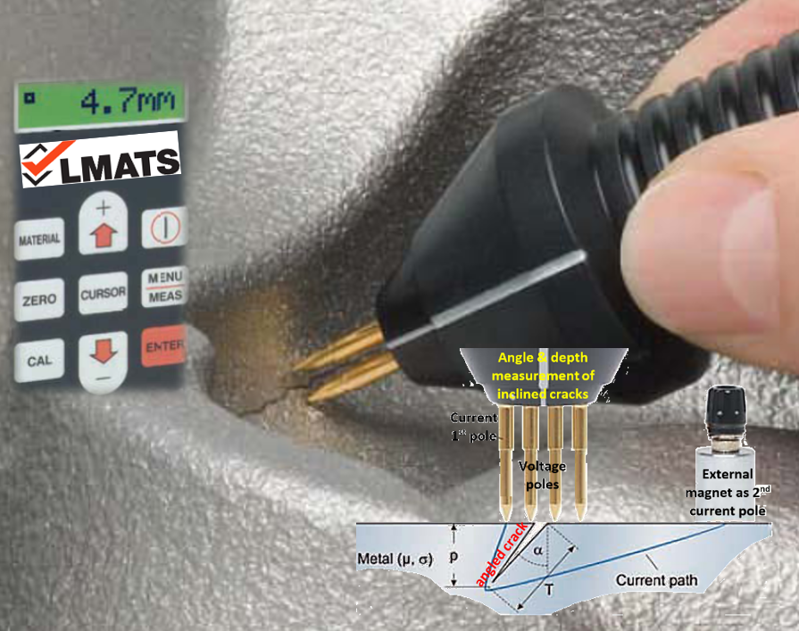
- For a crack depth measurement of inclined cracks, the frequency of the alternating current is automatically lowered so that the electric current covers a wider area in the workpiece.
- Depending on the position of the external current pole (positioned either left or right with respect to the crack) different voltage drops result, which are used to calculate the angle (orientation) of the crack.
- Prior to the test, ACPD is balanced by placing a probe on a defect free surface. A voltage is measured and compared with the stored values in the instrument’s calibration data. Accordingly, individual material characteristics are used by the instrument’s microprocessor in crack measurement process.
Critical Considerations:
- Surface coating must be removed for probe’s conductive contact.
- Demagnetisation of test surface is necessary, if ACPD is applied after other magnetic tests.
- Suitable for crack measurement only. Unsuitable for surface scanning or crack finding.
- Although only 500mA low pulsed current is applied, tiny sparks at the contact spots may occur.
- Electrical & magnetic properties of the material adjoining the crack shall be predominantly homogenous for a reliable measurement.
Expertise:
- LMATS experience in other electromagnetic test techniques (ET, ECA, ACFM) provides advantage to apply ACPD techniques accurately on different materials.
- Although ACPD may appear to be easy to use, understanding about various materials and field applications are important. Hence, this test method requires highly trained, skilled, and experienced personnel.
- LMATS has trained, certified and experienced personnel to provide ACPD testing services.
- LMATS offers ACPD testing from our Australia wide branches currently in Perth, Melbourne, Sydney, Newcastle, Albury, and Brisbane.
- LMATS regularly performs ACPD testing in VIC -Victoria, NSW - New South Wales, QLD - Queensland, WA - Western Australian, SA - South Australia, TAS - Tasmania, NT -Northern Territory and some of the neighboring countries at request.
- To find more about ACPD advanced NDT capability, contact one of LMATS laboratories nearest to your location or call 1300 707 365
Frequently asked Questions:
- FAQ1– Can ACPD be applied on all types of conductive metallic alloys?
Answer – Yes. ACPD can be applied on most conductive metallic alloys. For best, accurate and repeatable results, a reference block from the same material under test shall be used to calibrate instrument for the purpose of optimizing characteristics curve for magnetic and electrical properties or material under test.
- FAQ2– Can ACPD be used for surface scanning and crack detection?
Answer – ACPD is a precision crack depth measurement technique. This NDT method is not designed for large scale surface scanning and detecting cracks on the test surface. LMATS ECA – Eddy Current Array testing or ACFM – Alternating Current Field Measurement should be utilised.
- FAQ3– Is this true that ACPD can find orientation of cracks in the material?
Answer – It is true that ACPD can find orientation of surface breaking cracks in ferrous materials by using a special probe and technique. The resolution of the orientation is approximately ±10° resolution in steel. There are several limitations for the experiment in non-ferrous materials.
